Neotherm C
Coal, wood or briquette fired thermic fluid heater with external furnace and balanced draught — built for low-grade fuels.
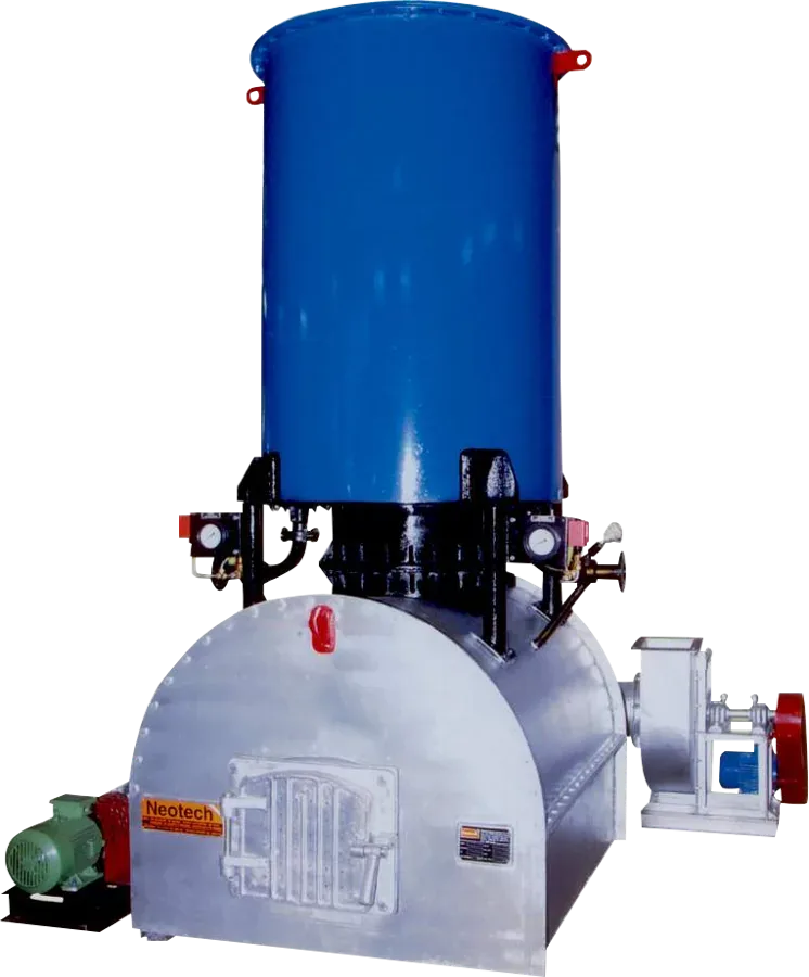
Built for the plant floor
- Three Pass Design
- Packaged Unit
- Multiple passes on fluid side ensure low pressure drop across the coil, thereby making more head available for process
- Good combustion efficiency
- Low heat release rate per unit furnace volume
- Easy access for inspection & cleaning
- High operating efficiency
- Low system lag & rapid warm up response
- Outside the purview of IBR
The thermic fluid system
A forced-circulation, fully automatic thermic fluid heater: the fluid is heated, delivered to the process and recirculated through the heater. It reaches fluid temperatures of up to 300 °C at near-atmospheric pressure.
The heater
The unit has a nest of concentric helical coils inside a sturdy mild-steel shell, an arrangement that gives optimum heat transfer. The main unit and its accessories sit on a sturdy steel skid, which makes installation easy.
External furnace & balanced draught
Fuel burns in an external furnace, which removes any hazard to the thermic fluid coil. A balanced-draught system gives very efficient combustion and good heat transfer. The FD fan supplies air to the whole combustion bed, and the optimised furnace has no dead pockets and very low inertia.
Designed for low-grade fuel
The furnace volume and bubble-nozzle bed are designed specifically for low-grade fuel with high ash content and low calorific value. Balanced draught burns the volatiles completely and reduces particle emission. Combined with the 3-pass design and a large heat-transfer surface, it gives a consistently high efficiency of over 70 %.
Applications
Technical specification — Neotherm C (solid fuel)
| Parameter | NTC:100 | NTC:200 | NTC:300 | NTC:400 | NTC:600 | NTC:1000 |
|---|---|---|---|---|---|---|
| Heat outputkcal/hr | 1,00,000 | 2,00,000 | 3,00,000 | 4,00,000 | 6,00,000 | 10,00,000 |
| Outlet temperature°C | 300 | 300 | 300 | 300 | 300 | 300 |
| Temperature rise in heater°C | – | 25 | 25 | 25 | 25 | 25 |
| Pressure at heater outletkg/cm² | 2.2 | 2.2 | 2.2 | 2.5 | 2.5 | 2.5 |
| Flue gas duct diametermm | 200 | 250 | 300 | 300 | 350 | 450 |
| Inlet / outlet connectionmm | 40 | 50 | 50 | 65 | 65 | 100 |
| Fuel consumption — coalkg/hr | 32 | 64 | 96 | 128 | 192 | 320 |
| Fuel consumption — woodkg/hr | 40 | 80 | 120 | 160 | 240 | 400 |
| Fuel consumption — briquettekg/hr | 32 | 64 | 96 | 128 | 192 | 320 |
| Thermic fluid pump motorhp | 5 | 7.5 | 10 | 10 | 15 | 20 |
| ID fan + FD fan motorhp | 1.5 + 0.5 | 2 + 0.5 | 2 + 1 | 3 + 1 | 5 + 2 | 7.5 + 3 |
| Total connected loadhp | 7 | 9.55 | 13 | 14 | 22 | 30.5 |
• Thermal efficiency 70 ± 2 %; with air preheater 76 ± 2 % (on NCV).
• NCV basis — coal: 4,500 kcal/kg · wood: 3,300 kcal/kg · briquette: 4,500 kcal/kg.
What comes with every unit
The standard supply package, the controls and safeties fitted as standard, and what we need at site, as listed in Neotech's scope of supply.
Main unit — standard scope
- Heat Exchanger (Coil): 3-pass design with liberal heat transfer area and adequate furnace volume, made from boiler-quality pipes, to achieve complete heat exchange from the flue gases of solid fuels such as coal or wood. Parallel coil passes ensure extremely low pressure drop, and a high thermic fluid velocity is maintained across the coil for an efficient rate of heat exchange. (Insulation of the unit to be carried out by others.)
- Furnace: fabricated from 10 SWG M.S. sheets with necessary angle supports, fitted with 1 fire door and 1 set of C.I. fire bars. (Refractory work to be carried out on site by others.)
- Air Preheater: multi-pass, counter-current-flow, shell & tube type, self-cleaning design, to preheat combustion air using flue gas heat for optimum thermic fluid heater efficiency.
- Expansion-cum-Deaerator Tank: specially designed, 1,000-litre capacity, fabricated from 3 mm & 5 mm plates with 2 interconnected separation & buffer vessels, complete with inlet/outlet connections, vapour-removal arrangement, drain and level indication. Fitted with 4 mounting lugs for installation at the desired height.
- Thermic Fluid Circulation Pump: motor-driven, coupled via a Love-Joy coupling, mounted on a base frame with drip-collection tray, coupling guard and water-cooling arrangement.
Control panel
- Control Console Box: dust- & vermin-resistant enclosure with rubber sealing for corrosion resistance, oven-baked painted finish for long life, floor-mounted type.
- Contactors & Overload Protection Relays (Telemecanique make) for the circulation pump, I.D. fan and F.D. fan motors, safeguarding against single-phasing.
- Main Switch & Programmer Switch for ON/OFF and programmed operation of the unit.
- Return Temperature Indicator-cum-Controller: digital electronic type with thermocouple and compensating cable for precise temperature control.
- Outlet Temperature Indicator-cum-Controller: digital electronic type with thermocouple and compensating cable, for precise monitoring and alarm actuation on abnormal outlet temperature.
- Pan-Alarm System (audio-visual, panel-mounted) for precise fault indication, covering: high outlet temperature; low T.F. pressure; high T.F. pressure; overload on T.F. pump; and overload on F.D./I.D. fan.
- MCB on Control Circuit (MDS / Indo Kopp make) to prevent malfunction due to short-circuit.
- Individual Fuse Units (Bharat Linder make, TP type) for the T.F. circulation pump, I.D. fan and associated motors.
Instrumentation & auxiliary equipment
- Instrument Panel: unit-mounted instrument box housing 2 pressure switches and 2 bakelite-moulded, 4″ dial pressure gauges to indicate pump and system pressure.
- I.D. Fan: belt-driven, with dynamically balanced impeller and bearing-supported shaft, for controlled air flow within the combustion chamber and venting of flue gases through the chimney.
- F.D. Fan: motor-driven, for supply of primary combustion air and efficient combustion.
- Inlet / Outlet Headers: flanged-end, with thermowells for temperature sensing and isolation valves for pressure lines, provided for pressure indication and low-pressure / high-pressure control switches.
Piping, wiring & documentation
- Internal piping and wiring for the unit — one set.
- Complete set of installation & operation manual, with wiring diagram, installation diagram, and foundation drawing for the Thermic Fluid pump, chimney, etc.
Battery limits
Thermic Fluid Heater
- Suction of Thermic Fluid Pump.
- Discharge of Thermic Fluid Pump.
- Inlet of Thermic Fluid Heater.
- Outlet of Thermic Fluid Heater.
- Terminal points of Expansion-cum-Deaerator Tank.
Electrical
- Terminal connections on control panel and circulating pump motor.
Air & Fuel Gas
- Suction of F.D. Fan.
- Suction / Discharge of I.D. Fan.
- Fuel gas outlet on heater body.
Get a quotation for Neotherm C
Tell us the duty, the fuel available and your location. An engineer will call back with a selection and a price, usually within one working day.
- Office: +91 22 2859 0678
- Factory: +91 98210 28660
- sales@neotechboilers.com
You may also need
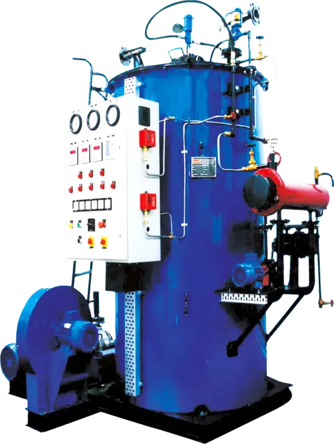
Neotherm
Oil Fired Thermic Fluid Heater
Vertical, fully automatic thermic fluid heater with four heat-transfer passes — 300 °C at the outlet, 88 % efficiency.
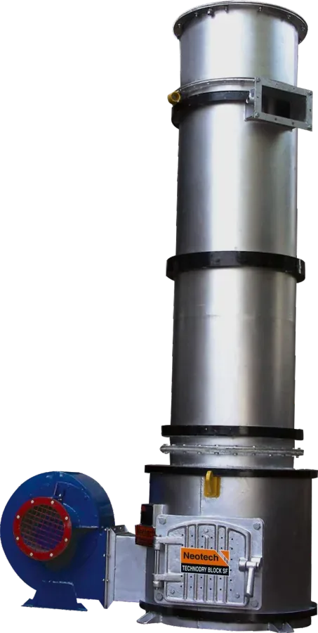
Technodry Block SF
Solid Fuel Fired Hot Air Generator
Indirect, fully automatic hot air generator firing wood, coal or agro-briquettes — clean hot air up to 200 °C.
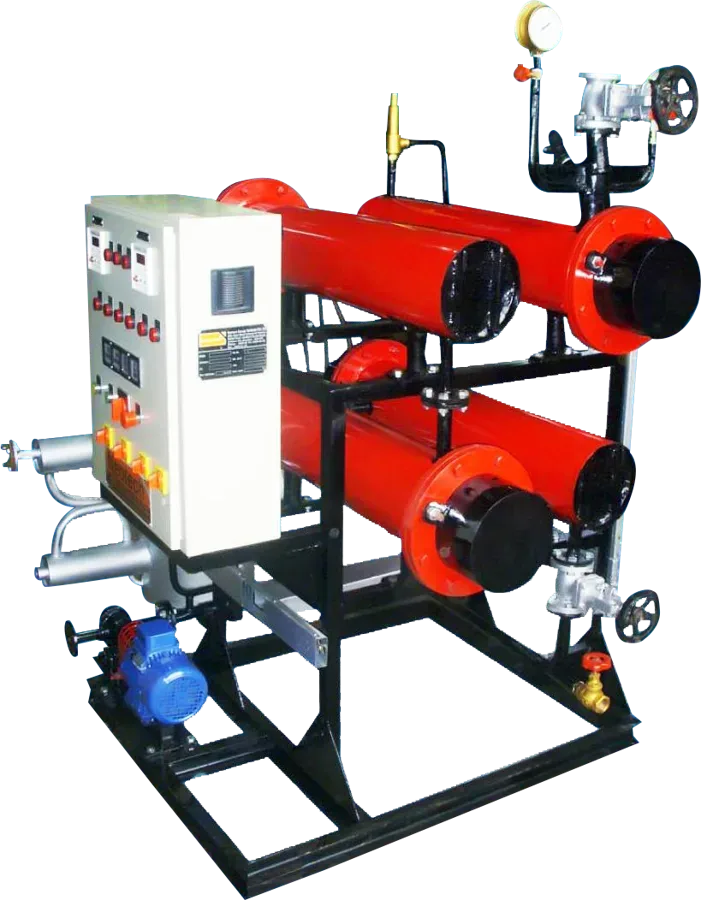
Neotherm E
Electrically Heated Thermic Fluid Heater
Skid-mounted electric thermic fluid heating system — 98 % efficient, 280 °C, no chimney, no fuel handling.